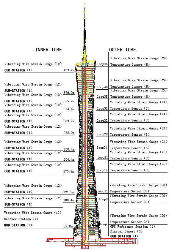
Figure 1. Sensor layout of the in-construction monitoring system
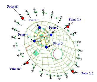
Figure 2. Location of strain monitoring points at each section
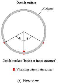
Figure 3. Location of vibrating wires on the outer tube
An extensive monitoring system is being constructed to guarantee the stability and safety of the structure during construction stage. In addition, this in-construction monitoring system will allow engineers and construction managers to ensure the geometric configuration of the constructed structure within the allowable deviation specified in the tower design. After completion of the tower, portions of the in-construction monitoring system will be integrated into the in-service monitoring system.
The in-construction monitoring system is composed of six functional modules: sensory system (SS), data acquisition and transmission system (DATS), data processing and control system (DPCS), structural health evaluation system (SHES), data management system (DMS), and inspection and maintenance system (IMS).
The SS is responsible to collect the raw data from the 16 various types of sensors. The DATS consists of thirteen stand-alone data acquisition units (sub-stations) for in-construction monitoring. Data acquisition units (DAUs) or sub-stations are indispensable to SHM systems for large-scale structures like GNTVT. They are assigned at 13 cross-sections of the tower to collect the signals from surrounding sensors, digitize the analog signals and transmit the data into a central room in wireless manner. The DPCS comprises high performance servers located in the central room and data processing software. It is devised to control the on-structure DAUs regarding data acquisition and pre-processing, data transmission and filing, and visualization of the data. The DMS comprises an Oracle-driven database system for temporal data management and a Geographic Information System (GIS) software system for spatial data management. The database system adopts a relational database approach while the GIS utilizes a node-arc-polygon structure. The SHES is composed of an on-line structural condition evaluation system and an off-line structural health and safety assessment system. The on-line structural condition evaluation system is mainly to compare the static and dynamic measurement data with the design values or pre-determined thresholds, FEM analysis results, and statistical patterns to provide a prompt evaluation on the structural condition. The off-line structural health and safety assessment system incorporates varieties of model-based and data-driven damage diagnostic and prognostic algorithms which mostly require both historical and current monitoring data. An inspection and maintenance system (IMS) is used for regular or emergent inspections and maintenance of the hardware and software of the entire system.
As listed in Table 1, the sensory system (SS) consists of 527 sensors in the construction stage. These sensors are deployed for monitoring of three categories of parameters: (i) loading sources (wind, seismic and thermal loading), (ii) structural responses (strain, displacement, inclination, acceleration, and geometric configuration), and (iii) environmental effects (temperature, humidity, rain, air pressure, and corrosion). Layout of sensors can be found in Figure 1.
The unique feature of the in-construction monitoring system is the use of wireless rather than wire-based data transmission. Wireless transmission allows for the monitoring system to be installed with great ease and great safety since the signal transmission lines are prone to be damaged by the construction activities of other contractors.
Table 1. Sensors deployed for in-construction and in-service monitoring
|
No. |
Sensor Type |
Monitoring Items |
Number of Sensors |
|
| In-Construction Monitoring | In-Service Monitoring | |||
|
1 |
Weather station |
Temperature, humidity, |
1 |
1 |
|
2 |
Anemometer |
Wind speed and direction |
2 |
2 |
|
3 |
Wind pressure sensor |
Wind pressure |
- |
4 |
|
4 |
Total station |
Inclination, leveling, |
1 |
- |
|
5 |
Zenithal telescope |
Inclination of tower |
2 |
- |
|
6 |
Tiltmeter |
Inclination of tower |
- |
2 |
|
7 |
Level sensor |
Leveling of floors |
2 |
- |
|
8 |
Theodolite |
Elevation |
2 |
- |
|
9 |
GPS |
Displacement |
2 |
2 |
|
10 |
Vibrating wire gauge |
Strain, shrinkage and creep |
416 |
60 |
|
11 |
Thermometer |
Temperature of structure |
96 |
60 |
|
12 |
Digital video camera |
Displacement |
3 |
3 |
|
13 |
Seismograph |
Earthquake motion |
- |
1 |
|
14 |
Corrosion sensor |
Corrosion of reinforcement |
- |
3 |
|
15 |
Accelerometer |
Acceleration |
- |
22 |
|
16 |
Fiber optic sensor |
Strain and temperature |
- |
120 |
| Total |
527 |
280 |
||
|
Figure 1. Sensor layout of the in-construction monitoring system |
Figure 2. Location of strain monitoring points at each section |
|
Figure 3. Location of vibrating wires on the outer tube |
Monitoring
of strain/stress and structural temperature
It is critical that strain and temperature of the tower is closely monitored
during construction so as to keep structural stress and deformation within allowable
limits and to ensure the safety and functionality of the structure. Based on
the preliminary results of a finite element analysis, 12 sections of the tower
with larger stress are chosen for monitoring during the construction stage.
As shown in Figure 1, the 12 sections are chosen at elevations of 32.8 m, 100.4 m, 121.2 m, 173.2 m, 204.4 m, 230.4 m, 272.0 m, 303.2 m, 334.4 m, 355.2 m, 376.0 m, and 433.2 m for the inner concrete structure. These elevations correspond to Ring No. 3, 9, 11, 17, 21, 24, 28, 32, 36, 37, 40 and 44 of the outer tubular structure. Sensor locations at each monitoring section are the same as those for the in-service monitoring system as shown in Figure 2.
For the outer structure, strain is monitored by vibrating wire strain gauges (see Figure 3). There are six vibrating wires at every monitoring location for the outer structure. Three of them are used to monitor the strain on the surface of the CFTs. From the plane view (see Figure 3a), they are placed vertically and on the inside surface of the CFT, forming angles of 60 degree (with respect to the column center) between the neighboring gauges. The fourth strain gauge is embedded inside the CFT to monitor the steel-concrete interactions. This strain gauge is not installed in the monitoring locations on the four lowest monitored rings (Rings 3, 9, 11, and 17), but on all the other monitored rings (Rings 21, 24, 28, 32, 36, 37, 40 and 44). The fifth gauge is placed at the midpoint and on the inside surface of the nearby brace (inclined supporting member) for monitoring the axial strain of the brace (see Figure 3b). The sixth strain gauge is installed at the midpoint and on the inside surface of the nearby segment of the ring bar.
The temperature inside the CFT is monitored by the vibrating wire temperature sensor. In order to monitor the temperature at the surfaces of the CFT, brace and ring bar, thermometers are used.
For the inner concrete structure, the sensor arrangement at each monitoring section is the same. A 45 degree strain-gauge rosette is placed at each monitoring point for monitoring the strain/stress of the concrete structure. The temperature of inner concrete structure is measured by the vibrating wire temperature sensors integrated with the vibrating wire strain gauges.
Monitoring
of tilt, levelness, elevation and horizontal displacement
In order to monitor the tilt (perpendicularity) of the tower, four points at
the podium level around the inner structure (two on the major axis and two on
the minor axis of the inner structure) are selected as reference points for tilt
measurement. Laser zenith meters are used to emit four laser beams from the
podium to the zenith. Control points on each floor of the tower that correspond
to the location of the four reference points on the podium are used to monitor
the tilt of the tower. A total station is used to locate these control points
with holes punched through every floor to allow the laser beam to freely
propagate without obstruction. For monitoring the levelness and elevation of
each floor, five control points are selected: the center and the four vertexes
of ellipse plane of the floor. Elevation of floor control points can be measured
through transit stations from the lower floors to the higher floors using a
theodolite and a total station. The levelness
of each floor will be validated using an theodolite and a level gauge. In addition,
a GPS rover station will be positioned at the cross-sectional center for measuring
elevation with the aid of a GPS reference station positioned at the tower's
podium level. Measurements of elevation by the GPS system can be verified with
the results obtained from traditional survey techniques using the theodolite
and total station. In order to minimize the influences of environmental factors,
it is preferable to conduct measurements at midnight or early morning when wind
and temperature conditions are relatively stable and other environmental factors
are minimum.
The horizontal displacement at the top of the tower and inter-story drifts should be controlled to be within allowable ranges. In order to monitor horizontal displacements, digital video cameras and the GPS system are used to measure the horizontal displacement at the top of the constructed structure, as shown in Figure 4. Three non-collinear targets are set on the top of the structure and three digital video cameras are installed on three observation points at the podium level to capture the movements of these targets. Movements of the inner tower in two horizontal directions and rotation along the centroid can then be calculated.
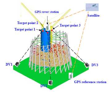
Figure 4. Combination of GPS and digital video camera for displacement measurement
Monitoring
of wind and weather conditions
For monitoring wind conditions, two sets of bi-directional anemometers are installed
at the top of the cranes. These sensors are uplifted with
the cranes as construction progresses. A weather station is positioned at the
top floor to monitor
the weather conditions. The weather station and anemometers will be moved
to the top of the main tower for long-term in-service monitoring after the completion
of construction.
Monitoring
of concrete shrinkage and creep
The concrete
shrinkage and creep induce additional deformation of the
structure. This should be removed from the measured total strain to obtain the
real stress of the structure due to external loadings. To obtain the real
shrinkage and creep, concrete specimens
were made with the same material ingredient and under the same curing conditions
with those used in the tower construction. A few vibrating wires were embedded
in in the specimens and the coefficients of shrinkage and creep can then be
obtained.