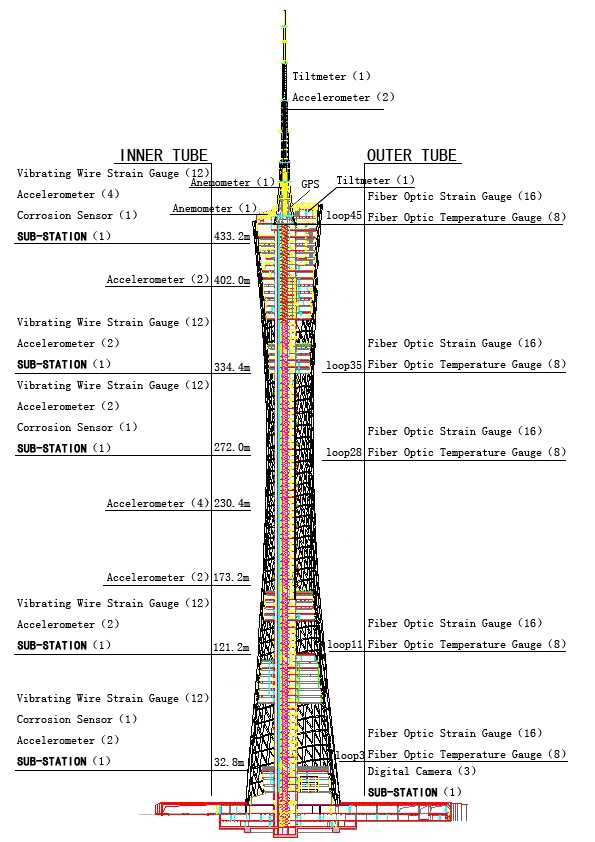

Figure 1. Sensor layout of the in-service monitoring system
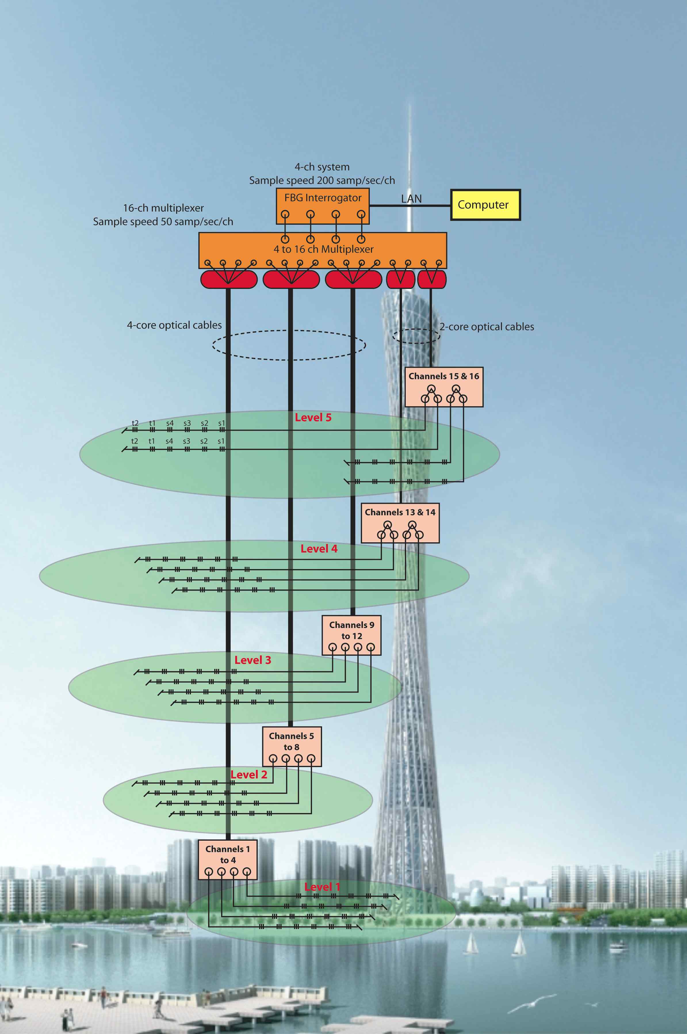
Figure 2. FBG Sensor layout
The instruments employed in the in-servicemonitoring are integrated with those in the in-construction monitoring with different focuses. The objectives of in-service monitoring include: 1) monitor the loadings and responses of the structure; 2) ensure structural performance meet the design requirements, 3) evaluate structural safety during the service stage, and 4) detect the existence and extent of possible damage that occurs during the tower's lifespan period. Similar to the in-construction monitoring system, the in-service monitoring system is composed of six functional modules: sensory system (SS), data acquisition and transmission system (DATS), data processing and control system (DPCS), structural health evaluation system (SHES), data management system (DMS), and inspection and maintenance system (IMS).
The SS consists of a weather station (measure air temperature, relative humidity, barometric pressure, and rainfall), anemometers (measure wind direction and speed), wind pressure sensors and a seismograph (measure the ground motion). These sensors are intended to monitor environmental conditions and quantify external loads. To monitor the response of the tower to these conditions and loads, vibrating wire temperature sensors (measure temperature of reinforced concrete members), fiber optic temperature gauges (measure temperature of steel members), vibrating-wire strain gauge (measure strains of reinforced concrete members), fiber optic strain gauge (measure strains of steel members), accelerometers, GPS, digital video cameras, and tiltmeters (measure the acceleration, displacement and inclination of the tower respectively) are being installed. For durability assessment, a suite of corrosion sensors are being installed to monitor the corrosion condition of the reinforced concrete tower. There exists in total 280 sensors in the monitoring system.
A more detailed discussion of monitoring content and corresponding sensor placements are detailed in the later sections. The major difference of the DATS from that of the in-construction system is the manner of data transmission. In the long term service stage, the system requires higher stability and reliability. To achieve this, the signals picked up by the fiber optic sensors are acquired by an interrogator situated in a local optical fiber network. Signals from the other sensors are acquired by the DAU located at five sub-stations through five optical fiber networks. Together, the optical sensors' interrogator and the five DAUs along with the local networks and a global Ethernet network constitute the complete DATS.
Monitoring
of strain/stress and structural temperature
Based on the preliminary results of a finite element analysis,
five sections of the tower with large stress are
chosen for monitoring. The specific locations are on the spiral ring bar (Ring
No.
3, 11, 28, 36 and 44) for the outer steel structures and at elevations 32.8
m, 121.2 m, 272.0 m, 334.4 m, and 433.2 m for the inner concrete structure,
as shown in Figure 1.
The monitoring points are quite similar to those employed in the in-construction monitoring system. The major difference lies in that 6 fiber optic sensors (FBG type) are used in the outer CFT columns at each point, in stead of vibrating wires. This is because the fiber optic sensors offer several unique advantages: (i) fiber optic sensors are immune to electromagnetic interference (this is extremely important for the tower that is used for TV signal transmission), (ii) many sensors could be multiplexed by wavelength division multiplexing along a single fiber, (iii) remote sensing up to 100 km is possible as fiber optic sensors are intrinsic devices created inside very low-loss optic fibers (<0.2 dB/km), (iv) signal fidelity is extremely high as wavelength is an absolute parameter which is not related to the signal power level; and (v) the wavelength of a FBG sensor is a signature of that particular FBG and it is also an absolute reference for measurement. 4 FBG sensors are used to measure the strain and another 2 is to measure the temperature at each monitoring point. Consequently there are 6*4*5=120 FBG sensors in total. The FBG interrogation system employs a wavelength-tunable fiber laser whose emission wavelength can be tuned at speed of 200 cycles per second with each cycle covering the entire reflection wavelength of the FBG sensors. The interrogator has four outputs which are extended to sixteen outputs using an optic multiplexer. Each of the sixteen channels covers 80 nm but operates at one fourth the original sampling speed (that is, 200/4=50 Hz). Topology of the system is shown in Figure 2.
 |
 |
|
Figure 1. Sensor layout of the in-service monitoring system |
Figure 2. FBG Sensor layout |
Monitoring
of Acceleration
In order to obtain the tower's dynamic response characteristics (modal frequencies,
mode shapes, and modal damping ratios) from field measurements, 20 accelerometers
are deployed at 9 sections. Of these 9 sections, eight correspond to the
main tower and one is to the antennary mast. The 8 accelerometer sections
of the tower are located at elevations 32.8m, 121.20 m, 173.2m, 230.4m,
272.0m, 334.4m, 402.0m, 433.2m and 484.0m.
Monitoring
of tilt and displacement
For monitoring the tilt (perpendicularity) of the tower between the lateral
and vertical directions within the elevation plane, two sets of bi-directional
tilt meters are deployed at the top of the main tower (454.00 m) and on the
mast (529.00 m). To monitor the displacement at the tower, a GPS system is
deployed with a rover station at the tower top (454.00 m) and a reference
station at the podium level. In addition, an additional measurement of the TV
tower top is accomplished by installing three digital video cameras deployed in
a non-collinear configuration at the podium level. These are identical to the In-construction monitoring system.
Monitoring
of ground motion, wind and weather conditions
A high-precision seismograph is placed at the base of the tower foundation so
that accurate measurement of ground motion can be made. The acquired data will
be used to correlate ground motions and structural responses and to verify the
earthquake spectrum used for seismic design. For monitoring the tower's wind
loads, two bi-directional anemometers are deployed at the top of the main tower
(at an elevation of 454.0 m) and on the mast where the elevation is 484.0 m (30
m above the tower top). In addition, four blaster pressure gauges are installed
at the top of the main tower (at an elevation of 454.0 m) for measuring the wind
pressures. A weather station is also deployed at the top of the main tower (at an elevation of 454.0
m) for monitoring weather conditions such as air temperature, relative humidity,
barometric pressure, and rainfall.
Monitoring
of corrosion condition
In order to evaluate the durability of the concrete, the tower
will be monitored to detect corrosion conditions. Three monitoring sections
at elevations 272.0 m, 334.4 m and 433.2 m, respectively, are installed
with one corrosion sensor (an anode ladder system) at each section. A portable
data acquisition system is used to manually collect the corrosion information
from these corrosion sensors once a year. Acquired data from the anode ladder
systems will be used to quantify the structure's corrosion condition and to
evaluate its durability and safety.